DATA SHEET
SkelMod 51V / 54V188F
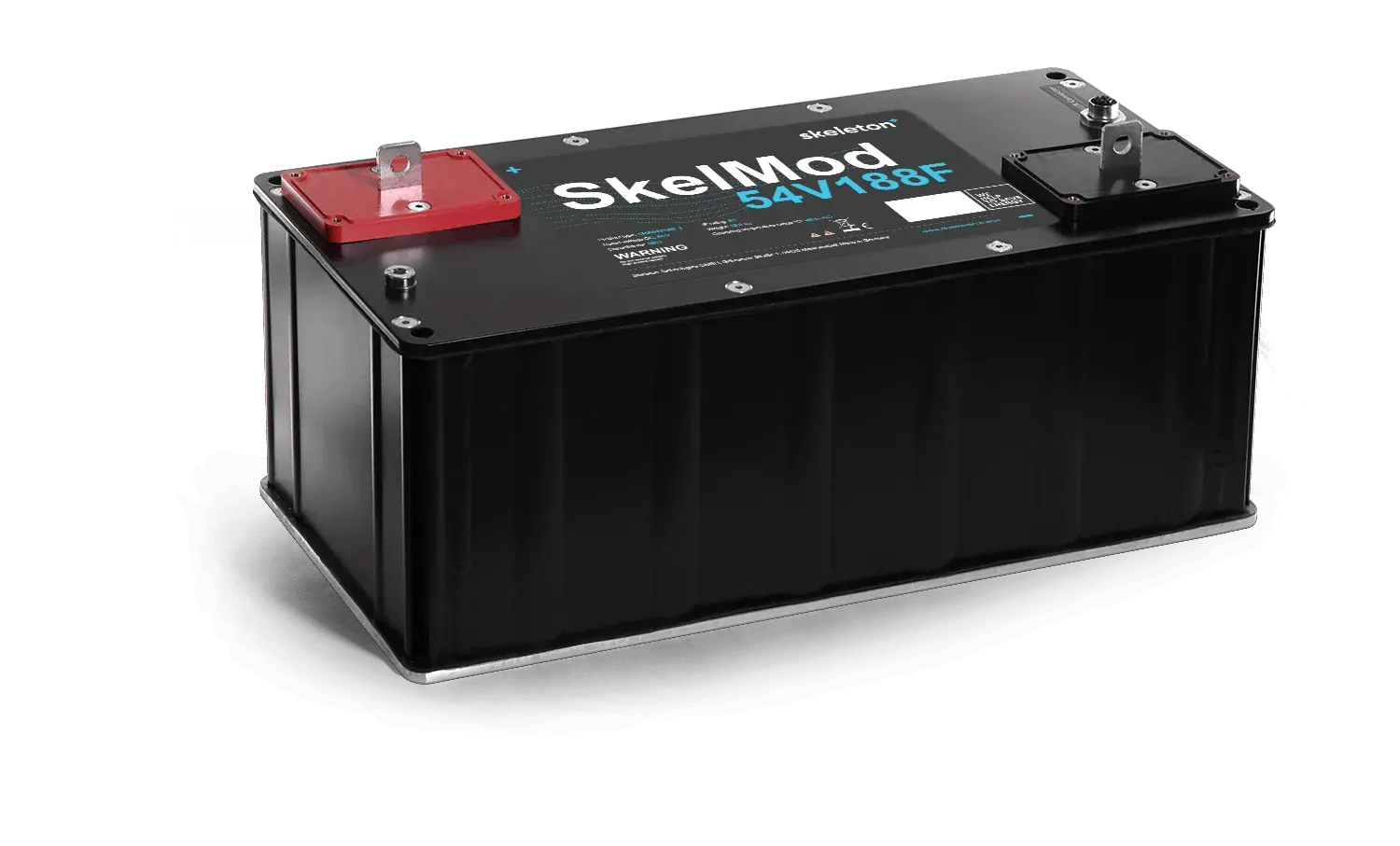
- 51V and 54V DC nominal voltage versions
- Rail-certified
- Ultra-low ESR
- Long lifetime - 1 million duty cycles
- Integrated Supercapacitor Management
- System for effective cell balancing
- CAN bus communication
- Natural cooling
- High Power output
- IP65
| Electrical – 51V 188F | Value | Unit |
|---|---|---|
| Rated voltage VR | 51 | V |
| Rated capacitance | 188 | F |
| Rated DC 10ms ESR | 3.0 | mOhm |
| Rated DC 1s ESR | 3.4 | mOhm |
| Rated max. peak current (for 1s duration) | 3.12 | kA |
| Maximum stored energy | 67.92 | Wh |
| Power, calculated from 1s ESR | 162.6 | kW |
| Temperature | Value | Unit |
|---|---|---|
| Operating temperature range | ||
| Operating temperature range, Minimum | -40 | °C |
| Operating temperature range, Maximum | +65 | °C |
| Storage temperature range (uncharged) | ||
| Storage temperature range (uncharged), Minimum | -40 | °C |
| Storage temperature range (uncharged), Maximum | +50 | °C |

| Electrical – 54V 188F | Value | Unit |
|---|---|---|
| Rated voltage VR | 54 | V |
| Rated capacitance | 188 | F |
| Rated DC 10ms ESR | 3.0 | mOhm |
| Rated DC 1s ESR | 3.4 | mOhm |
| Rated max. peak current (for 1s duration) | 3.12 | kA |
| Maximum stored energy | 76.14 | Wh |
| Power, calculated from 1s ESR | 162.6 | kW |
| Life | Value | Unit |
|---|---|---|
| Lifetime @ 51V and maximum operating temperature | 1500 | Hours |
| Lifetime @ 48V and maximum operating temperature | 2500 | Hours |
| Storage life @ RT, uncharged | 10 | Years |
| Projected cycle life @ RT, between 51V and 25.5V | 1,000,000 | Cycles |
| Projected cycle life @ RT, between 48V and 24V | 2,000,000 | Cycles |
| Supercapacitor management system | Value; Unit |
|---|---|
| Cell balancing method | Controlled Resistive Balancing |
| Temperature reading | 4 NTC sensors |
| Voltage monitoring/balancing | Individual cells |
| Nominal auxiliary supply voltage (EN 50155:2021) | 24 V |
| Auxiliary supply voltage range (EN 50155:2021) | 16 – 33 V |
| Interruptions on power supply voltage class (EN 50155:2021) | S2 (10 ms) |
| Supply change over class (EN 50155:2021) | C1 – 14.4V for 100 ms |
| Auxiliary supply current at nominal voltage | Max. 0.1 A |
| Inrush current | 0.00156 I2t |
| Supercapacitor monitoring range | 4 - 54 V |
| Maximum allowed cell imbalance for module discharge to 0V | 0.3 V* |
| Normally open fault line maximum allowable current | 0.1 A |
| Communication interface | Can bus 2.0B, non-isolated |
| Communication protocol | SAE J1939 |
| Standards (railway application) | Value |
|---|---|
| Insulation coordination | EN 50124-1:2017 |
| Environmental conditions | EN 50125-1:2014 |
| Electromagnetic compatibility | EN 50121-3- 2:2016+A1:2019 |
| Fire protection | EN 45545- 2:2020+A1:2023 |
| Electronic equipment requirements | EN 50155:2021 |
| Standards | Value |
|---|---|
| Degrees of protection provided by enclosure | EN 60529:2001/ A2:2014/AC:2019 |
| Ingress protection (EN 60529:1991+A2:2014+AC:2019) | IP65* |
| Shock and vibration class (EN 61373:2010+AC:2017- 09) | 1B |
| System-level electrical parameters (EN 50124-1:2017 & EN 60077-1:2017) | Value; Unit |
|---|---|
| Maximum series working voltage | 750 V DC |
| Rated isolation voltage | 900 V DC |
| Rated impulse voltage | 5 kV |
| Overvoltage category | OV2 |
| Pollution degree | PD4* |
| Connectors | ||
|---|---|---|
| Power connector | Ø 9mm through hole | |
| Communications connector on the device | Phoenix Contact female M12; X-coded 8-pos (Mfg part #:1424177) |
| Environmental conditions | ||
|---|---|---|
| Altitude class (EN 50125-1:2014) | A1 – 1400 m from sea level | |
| Yearly average relative humidity (EN 50125-1:2014) | 75% |
| Thermal | Value | Unit |
|---|---|---|
| Thermal resistance given at ΔT 30 °C (Rth) | 0.41 | °C/W |
| Thermal capacitance (Cth) | 18 | kJ/°C |
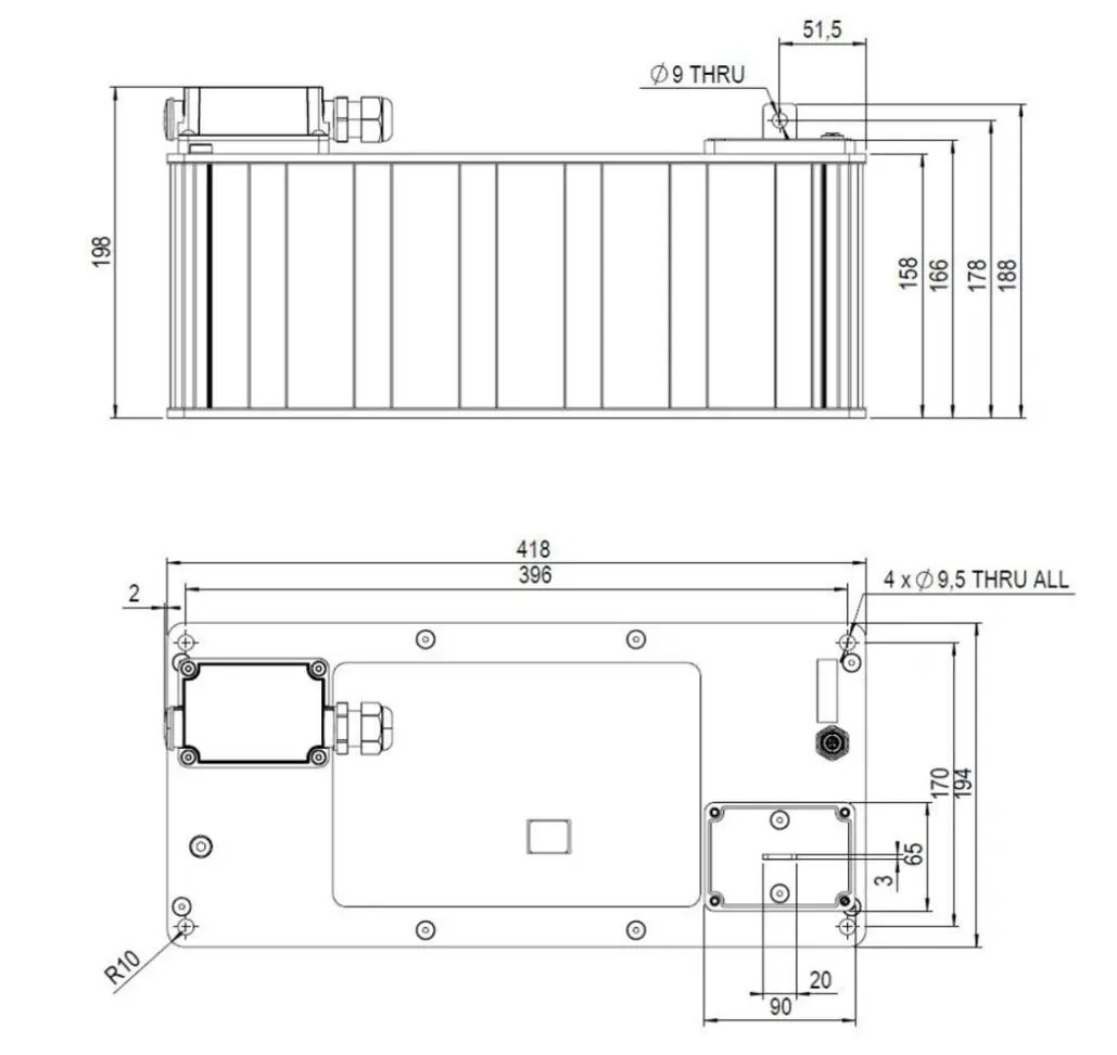
| Physical parameters | Value | Unit |
|---|---|---|
| Mass, typical | 16 | kg |
| Volume | 13.5 | L |
| Length x width x height | 422 x 194 x 198 | mm |
Notes
Capacitance decrease 20% from rated value;
resistance increase 100% from rated value.
*Refer to user manual for additional information.
*With IP covers installed on the power terminals, otherwise PD3
Standard markings
Name of manufacturer, part number, serial number, rated voltage
Rated capacitance, negative and positive terminals, warning marking
Total energy in watt-hours
Notes
All information provided on this data sheet and all subsequent supercapacitors sales and testing are subject to Standard Terms of Service (ToS) available on www.skeletontech.com, document General Terms of Sale for Skeleton Technologies GmbH
For supercapacitors, the power values are often calculated using nominal resistance values (DC 10 ms ESR). For engineering purposes, practical values based on total resistance (DC 1s ESR) are preferred.
All calculated values according to beginning-of-life conditions.
Mounting Recommendation: Please refer to the user manual for installation recommendations.
No cables included with the modules.
IP covers not included, sold as separate components, part #:
IP covers kit - 7100026 (including red and black covers, cable glands and fasteners for the covers)